Why Chiller and Boiler Predictive Maintenance Has a Sensor Problem
Unplanned chiller failure during peak cooling season is among the most expensive maintenance events a facility can experience. An emergency replacement of a centrifugal chiller compressor or a condenser tube bundle in August, with expedited equipment delivery and overtime labor, easily exceeds six figures. Beyond the direct repair cost, the downstream consequences — hot floors, disrupted operations, potential equipment damage in server rooms or laboratory spaces without backup cooling — can dwarf the mechanical repair bill itself.
Predictive maintenance programs exist to detect failure precursors before catastrophic failure occurs. The challenge is not the data analysis — condition monitoring algorithms for rotating equipment are well-established. The challenge is instrumentation. Permanently wired vibration transducers and thermal sensors on every motor, pump, and fan coil unit in a large building require significant electrical infrastructure investment. In practice, most facilities either instrument only the largest and most critical assets (the primary chillers) or rely on periodic manual vibration surveys (monthly walkthroughs with a portable vibration analyzer), which miss the failure window that develops over days or weeks between survey visits.
Wireless mesh-connected vibration and temperature sensors change this economics. The MK-NODE vibration/thermal sensor attaches magnetically to a motor housing or bearing housing, provisions to the mesh in minutes, and begins reporting continuously without conduit runs or dedicated wiring circuits. The question then becomes: which sensors, placed where, measuring what, at what sample rates? That is a harder question than the hardware selection.
Vibration Sensing: Accelerometer Bandwidth and Sampling Rate
Vibration measurement for rotating equipment fault detection requires an accelerometer with adequate frequency bandwidth to capture the fault frequencies of the specific equipment type. For a centrifugal chiller with a 3,600 RPM compressor (60 Hz fundamental), the bearing fault frequencies (BPFO, BPFI, BSF, FTF — see below) typically fall between 50 Hz and 500 Hz. Resonance frequencies of the chiller casing and piping connections can extend relevant content up to 2–5 kHz. A MEMS accelerometer with a flat response to 1 kHz will capture most bearing faults on low-to-medium speed rotating equipment; an accelerometer extending to 10 kHz is needed for high-speed compressors and gearboxes.
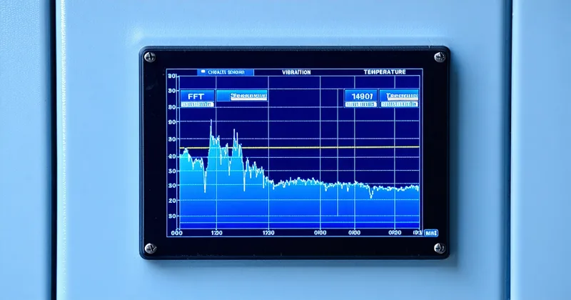
Sampling rate follows from bandwidth by the Nyquist criterion: to capture content at 5 kHz, the ADC must sample at ≥10 ksps. The MK-NODE vibration module supports up to 16 ksps on-chip, which covers the relevant frequency range for most commercial HVAC equipment. However, continuous sampling at 16 ksps generates approximately 32 KB/second of raw data per axis — impractical to stream across a mesh network and store at any density. The node performs on-board FFT computation, storing and transmitting spectral summary data (RMS by frequency band, peak frequency components, velocity RMS in mm/s) rather than raw time-series waveforms. This dramatically reduces data volume while preserving the diagnostic information needed for fault detection.
The Four Bearing Fault Frequency Families
Rolling element bearing faults produce vibration signatures at characteristic frequencies that depend on the bearing geometry and shaft rotation speed. The four fault frequency families are:
- BPFO (Ball Pass Frequency, Outer Race): energy at this frequency indicates damage to the outer bearing race. Formula: BPFO = (N/2) × Rpm/60 × (1 − d/D × cos α), where N is the number of rolling elements, d is ball diameter, D is pitch diameter, α is contact angle.
- BPFI (Ball Pass Frequency, Inner Race): inner race damage. Higher frequency than BPFO for the same bearing; sidebands at shaft frequency are characteristic.
- BSF (Ball Spin Frequency): rolling element (ball or roller) damage. Typically lower amplitude than race faults; BSF sidebands at cage frequency.
- FTF (Fundamental Train Frequency): cage fault or uneven loading. Lowest of the four families; often appears with sub-harmonic content.
In practice, fault detection does not require computing exact theoretical fault frequencies for every bearing in a mixed asset fleet. The more practical approach is baseline trending: establish a clean vibration spectrum during a post-maintenance period when bearings are known good, then monitor for spectral changes in the 100–2000 Hz range over time. A bearing approaching failure will show progressively increasing broadband RMS energy in the bearing fault frequency region before discrete fault-frequency peaks become clearly visible — the broadband trend threshold often provides earlier warning than waiting for clear spectral peaks.
ISO 10816 and Velocity RMS Thresholds
ISO 10816 (Mechanical Vibration — Evaluation of Machine Vibration by Measurements on Non-rotating Parts) provides velocity RMS severity zones for different classes of rotating equipment. Zone A (0–2.3 mm/s RMS for Class I machines — smaller motors and pumps under 15 kW) represents new installation condition. Zone B (2.3–4.5 mm/s) is acceptable for long-term operation. Zone C (4.5–7.1 mm/s) requires investigation; operation may continue short-term. Zone D (above 7.1 mm/s) requires immediate corrective action.
For commercial HVAC equipment — chiller compressor motors, cooling tower fan motors, condenser water pumps — the relevant ISO 10816 class depends on shaft power and mounting rigidity. A 200 kW chiller compressor motor with rigid base mounting falls under Class II or Class III in ISO 10816-3, with correspondingly higher zone thresholds than a small circulator pump. Correctly classifying each asset against the ISO standard before setting alert thresholds is a step that is often skipped in quick-start deployments; the result is either false alerts on healthy assets (too conservative thresholds) or missed faults (thresholds set too high from experience on larger equipment).
Temperature Sensing: What to Measure and Where
Vibration measurement detects mechanical faults in rotating components. Temperature measurement catches a different failure mode class: electrical faults (overloaded windings, failing insulation causing elevated motor temperature), lubrication failures (overheating bearings before vibration signatures are detectable), and heat exchanger fouling (elevated refrigerant temperatures indicating condenser tube scaling or evaporator fouling).
Bearing temperature measurement requires the sensor to be within 20–30 mm of the bearing housing surface; at that distance, surface temperature reflects bearing operating temperature with a lag of a few minutes. The MK-NODE's thermal module uses a surface contact thermistor rather than an infrared pyrometer for bearing housing monitoring — contact measurement is more accurate on metallic surfaces with variable emissivity and avoids the IR cross-talk issues that occur when multiple motors are mounted close together. For motor winding temperature, a PT100 RTD embedded in the winding itself (installed at motor commissioning or rewind) provides the most accurate data, but on motors without pre-installed winding temperature sensors, surface-mounted thermistors on the motor frame provide a useful proxy for thermal trend monitoring.
A Chiller Plant Instrumentation Scenario
A large university facility plant room contains two 400-ton centrifugal chillers, two 200-ton cooling towers, three condenser water pumps, and three chilled water pumps. Pre-deployment, the maintenance team runs quarterly oil sampling on the chiller compressors and does monthly vibration surveys on the pumps with a portable analyzer. This catches roughly 60–70% of developing faults, based on the facility team's historical incident data — the remainder are found during failure events or by the chiller controller's own built-in protection alerts, which trip the machine rather than provide early warning.
A wireless vibration and temperature deployment adds 18 MK-NODE sensors: two per chiller compressor bearing set (drive end and non-drive end), one per pump motor, and one on each cooling tower fan gearbox. Nodes provision to a Thread mesh served by two MK-GW gateways in the plant room; the concrete walls required placing one gateway inside the plant room and one at the mechanical room door, with a relay node bridging the signal through the steel door threshold.
Within the first 60 days of continuous monitoring, the vibration trend on one condenser water pump (pump CWP-2) shows a progressive increase in RMS energy in the 150–300 Hz band — consistent with developing outer race fault on the motor drive-end bearing. The trend crosses the Zone C threshold on a Thursday; the facility team schedules a bearing replacement for the following Monday morning during low-occupancy hours. At replacement, the extracted bearing shows visible outer race pitting — a fault that was approximately 3–4 weeks from progressing to a catastrophic failure based on the rate of RMS increase.
Motor Current Signature Analysis as a Complement
Vibration and temperature sensors detect mechanical fault signatures. Motor Current Signature Analysis (MCSA) detects electrical fault signatures — specifically, asymmetries in the three-phase motor current waveform that indicate broken rotor bars, eccentricity, or developing winding insulation faults. MCSA does not require physical contact with the motor shaft or housing; the current sensor clamps to the power supply conductors at the motor control cabinet.
We are not saying MCSA replaces vibration sensing. The two techniques are complementary: MCSA catches electrical fault modes that vibration sensing misses (rotor bar cracks, early winding insulation degradation), while vibration sensing catches mechanical faults (bearing wear, misalignment, imbalance) that do not necessarily produce significant current signatures until they are well advanced. A comprehensive predictive maintenance program for critical HVAC plant uses both. For a facility prioritizing initial instrumentation budget, vibration and temperature sensing on bearings and motor housings covers the highest-frequency fault modes first; MCSA can be added as a second phase on the highest-criticality assets.